

Object Oriented Optical Element Driving Project
Preliminary Discussion of common interface to OEs/Beamline Components
| The following generic class types have been identified. A number of these have moveable elements. After some discussion of the difference between a general beamline component and an optical element we don't believe there is a significant difference to warrant separate classification. |
| Generic Type | Beamline Component | Specific moveable parameters |
| Slit | TwoJaw GangedJaw Kratky Xtree |
|
| Mirror | Torroidal Flat |
|
| Monochromator | DCFSM Double Crystal Triangular |
|
| Table | 4-Axis 2-Axis 1-Axis |
|
| Sample selection | XY-stage Carousel |
|
| Sample orientation | Goniometer Diffractometer |
|
| Sample environment | Temp-Control Water bath Pressure Control Vacuum Gauge Attenuator Undulator |
|
| Detector | CCD ImagePlate PDA Area PMT Pin-diode Ion Chamber BPM TVM PSD |
Moveable components would potentially support a standard set of 3 rotations about and 3 translations along the axes as defined below.

|
Additionally the generic types would have a number of specific moveable parameters. Each of these parameters will need to be adjustable. Corresponding to each motion there would be a common set of methods e.g. get, set, moveBy (relative) and moveTo (absolute) methods. Parameters such as Yaw, Roll and Tilt are in actual fact just synonyms for the previously mentioned rotations. There is however likely to be dispute over which rotations. Our standard definition would be as follows. If this causes serious dispute then these should probably be disregarded. Such details would then be left to the developers of specific clients.
Not all implementations of say the mirror interface will support adjustment of all the standard parameters i.e. not all mirrors can be rotated about say the Y axis. Clients making use of movable classes will need to be able to deal with this. There will have to be some means of determining the capabilities of a class. A number of possibilities exist here
Two means of access to the motions of beamline components will be required
A number of possible status codes for beamline component adjustments have been identified. Attempts to move beamline components will return a code representing one on these states.
In an attempt to summarise the above and make sure its clear below is an example of what a Slit interface might look like. |
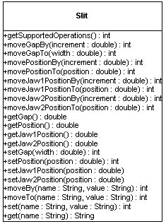 |