SAXS beamline
Small Angle X-ray Scattering has become a well known standard method to study the structure of various objects in the spatial range from 1 to 1000 nm, and therefore instruments capable to perform such experiments are installed at most of the synchrotron research centers.
The highflux SAXS beamline at Elettra has been built by the Institute of Biophysics and Nanosystems Research (IBN), Austrian Academy of Sciences, and is in user operation since September 1996.
On 1st October 2012 the beamline was transfered from the IBN to the Institute of Inorganic Chemistry of Graz University of Technology. The beamline was mainly intended for time-resolved studies on fast structural transitions in the sub-millisecond time region in solutions and partly ordered systems with a SAXS-resolution of 1 to 140 nm in real-space. But increasingly also grazing incidence (GISAXS) measurements are performed to study self-assembly processes on surfaces, or to perform structural characterizations of thin films.
The photon source is the 57-pole wiggler whose beam is shared and used simultaneously with a Macromolecular Crystallography beamline. From the very intense wiggler radiation, the SAXS Beamline accepts 3 discrete energies, namely 5.4, 8 and 16 keV (0.077, 0.154, 0.23 nm). The beamline optics consists of a flat, asymmetric-cut double crystal monochromator and a double focusing toroidal mirror.
A versatile SAXS experimental station has been set-up, and an additional wide-angle X-ray scattering (WAXS) detector can monitor simultaneously diffraction patterns. The sample station is mounted movable onto an optical table for optimising the sample detector distance with respect to SAXS resolution and sample size. Besides the foreseen sample surrounding, users have the possibility to install their own specialised sample equipment. In the design phase, besides technical boundary conditions, user friendliness and reliability have been considered as important criteria.
In conclusion, due to the highly variable kept sample stage, there are nearly no limits for the realization of an experiment, and you are welcome by our team to propose any interesting and high-lighting investigation for the benefit of material and life sciences.
 |
|
|
|
|
|

|
You are welcome to visit our beamline by clicking on the blue fields under the SAXS beamline sketch.
More detailed informations you can find in the following publications:
H. Amenitsch, S. Bernstorff and P. Laggner,
High Flux Beamline for Small Angle X-Ray Scattering at Elettra ,
Rev. Sci. Instrum. 66, 1624-1626 (1995)
H. Amenitsch, B. Hainisch, P. Laggner and S. Bernstorff,
The Potential of Asymmetric Monochromator Crystals for use in High-Power Insertion-Device Beamlines,
Synchrotron Radiation News 8.4, 22-27 (1995)
|
H. Amenitsch, S. Bernstorff, M. Rappolt, Kriechbaum, H. Mio and P. Laggner,
First Performance Assessment of the SAXS Beamline at Elettra,
J. Synchrotron Rad. 5 (1998) 506-508
S. Bernstorff, H. Amenitsch and P. Laggner,
High -Throughput Asymmetric Double-Crystal Monochromator of the SAXS Beamline at Elettra ,
J. Synchrotron Rad. 5 (1998) 1215-1221
|
1. General
|
|
Usually a (smaller) sample holder is mounted onto the sample alignment stage which allows the user to place the sample into the beam with a precision of 5µm (resolution: 1µm). The Figure shows the maximum possible dimensions, and alignment range, for a sample holder to be mounted via a base-plate onto our standard alignment stage (left), and dimensions of the base-plate (right). The maximum weight on the sample stage is limited to 10 kg.
In case the space requirements for a sophisticated sample station provided by the users are larger than those given in the Figure, the user can discuss with the beamline scientists for alternatives: if necessary, user equipment can also be mounted directly onto an optical table, which allows much larger spatial dimensions.
|
|
|
2. Standard sample holder
As standard equipment for liquid samples glass or quartz capillaries (diameter: 1, 1.5 or 2 mm) are used thermostated within a KPR (Peltier heating/cooling) sample holder (Anton Paar, Graz, Austria). For use in this sample holder closed capillaries can be used. But also flow through capillaries and Gel holders are standard equipment. Temperature scans can be performed with the KPR (0-70 °C). Typically the precision and the stability of this system is 0.1 °C. Additionally thermostats for temperature control or cooling proposes can be used at the beamline (-40 - 200 °C). Nitrogen and Argon gas is available at the beamline, for other gases please contact the beamline local contacts (generally, other gases should be provided by the users).
At present also a multiple-sample holder is available for measuring in automatic mode up to 30 solid samples at ambient temperature.
3. Flow-through capillary setup
The flow through cell works in a simple manner: Special quartz capillaries (Glas Technik & Konstruktion, Schönwalde/Berlin) of 1.5 mm diameter and wide openings of about 3 mm at each end, can be inserted into the standard Anton Paar sample holder, which allows various temperature treatments (T-range 25-300 or –30-70 °C, respectively). Thin tubes are connected directly to the capillary ends and a constanst flow is achieved by a peristaltic pump.
4. Stopped Flow Apparatus
|
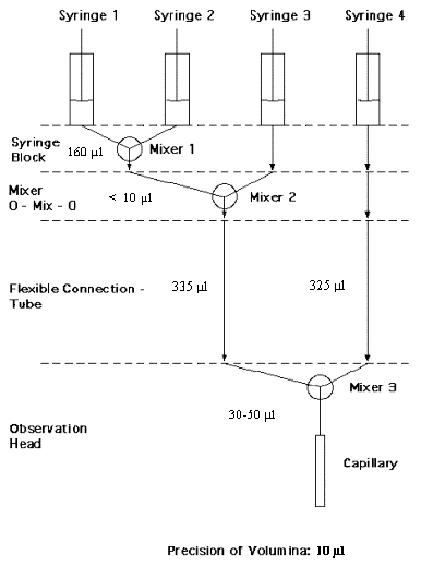
A commercial stopped flow apparatus (manufactured by Bio-Logic, Paris, France), especially designed for Synchrotron Radiation SAXS investigations of conformation changes of proteins, nucleic acids and macromolecules, is available. The instrument consists of a 4-syringe cell with 3 mixer modules manufactured by Bio-Logic. Each syringe is driven independently from the others by an individual stepping-motor, which allows a high versatility of the mixing sequence (flow-rate, flow duration, sequential mixing). For example, injection sequences using one or up to 4 syringes, unequal filling of syringes, variable mixing ratio, reaction intermediate ageing in three- or four-syringe mode etc.. The solution flow can be entirely software-controlled via stepping motors, and can stop in a fraction of a millisecond.
The software allows the set-up of the shot volumes of each of the 4 syringes in a certain time interval. Up to 20 mixing protocols can be programmed. Additionally macros for the repeated execution of individual frames can be defined. Furthermore, the input and output trigger accessible for user operation can be programmed. In the usual operation modus the start of rapid mixing sequence is triggered from our X-ray data-acquisition system (input trigger).
After the liquids have been rapidly mixed, they are filled within few ms into a 1 mm quartz capillary - situated in the X-ray beam- , which is thermostated with a water bath. Depending on the diffraction power of the sample time resolutions of up to 10 ms can be obtained.
|
|
 |
The main parameter of the system are:
· Thermostated quartz capillary (1 mm)
· Temperature stability 0.1 °C
· Total sample used per mixing cycle (shot volume): 100 µl
· Maximum 2qangle of 45°
· Total Volume 8 ml
· Dead volume 550 µl
· Flow rate: 0.045 – 6 ml/s
· Duration of flow 1 ms to 9999 ms/Phase
· Dead time: 1 ms
· Reservoir volume: 10 ml each
Further information can be found at the webpage: http://www.bio-logic.fr/
|
|
5. Online Exhaust System
At the experimental station is available a custom-built fume cover and chemical exhaust system for toxic gases. Thus it is possible to e.g. study in-situ chemical reactions, during which toxic gases might develop.
6. Grazing Incidence Small Angle X-ray Scattering
Grazing incidence studies on solid samples, thin film samples or Langmuir-Blodget-films can be performed using a specially designed sample holder, which can be rotated around 2 axes transversal to the beam. Furthermore the sample can be aligned by translating it in both directions transversal to the beam. The precisions are 0.001 deg for the rotations and 5 mm for the translations. Usually the system is set to reflect the beam in the vertical direction. According to the required protocol and the actual assembly of the rotation stages w, q, 2qand jscans can be performed.
|
|
|
|
|
7. Temperature Gradient Cell
|
|
|
A temperature gradient cell for X-ray scattering investigations on the thermal behaviour of soft matter manybody-systems, such as in gels, dispersions and solutions, has been developed. Depending on the adjustment of the temperature gradient in the sample, on the focus size of the X-ray beam and on the translational scanning precision an averaged thermal resolution of a few thousands of a degree can be achieved.
|
|
|
8. IR-Laser T-Jump System for Time-Resolved X-ray Scattering on Aqueous Solutions and Dispersions
The Erbium-Glass Laser available at the SAXS-beamline (Dr. Rapp Optoelektronik, Hamburg, Germany) delivers a maximum of 4 J per 2ms pulse with a wavelength of 1.54 µm
onto the sample. The laser-beam is guided by one prism onto the sample, which is filled in a glass capillary (1 or 2 mm in diameter) and Peltier or electronically thermostated in a metal sample holder (A. Paar, Graz, Austria). With a laser spotsize of maximal 7 mm in diameter a sample-volume of maximal 5.5 µl or 22 µl, respectively, is exposed to the laser-radiation. In a water-solutions/dispersions with an absorption coefficient of A = 6.5 cm-1 T-jumps up to 20°C are possible. |
|
|
|
9. High Pressure Cell System
SWAXS measurements of samples under pressure can be performed from 1 to 2500 bar, from 0 to 80 °C in the scattering angle region up to 30 degrees, both in the static or time-resolved mode, e.g. p-jump or p-scan, with a time-resolution down to the ms range. Precise pressure scans of any speed within a broad range (e.g. ca. 1.0 bar/s - 50 bar/s in the case of water as pressurising medium, and a typical sample volume) can be performed. Alternatively, dynamic processes can be studied in pressure-jump relaxation experiments with jump amplitudes up to 2.5 kbar/10ms in both directions (pressurising and depressurising jumps). In most applications diamond windows of 0.75 mm thickness (each) are used. The transmission of one pair (entrance and exit window) is 0.1 at 8 keV, i.e. lower than 0.3, the value for the originally used 1.5 mm thick Be-windows. However the loss in intensity is more than compensated for by the considerably lower background scattering of diamond thus leading to higher q-resolution in the experiments. The sample thickness can be 0.6-4.0 mm, with a volume of approximately 0.5-3 mm3 completely irradiated by pin-hole collimated (< 1.0 mm diameter) X-rays. The pressure cell system is flexible and can be built according to the needs of the particular experiment. Normally, a liquid (water, ethanol or octanol) is used as pressurising medium. But in principle, also gaseous media can be employed as well. N2 has been successfully tested, and measurements in supercritical CO2 became frequent. Beside bulk measurements on samples in transmission set-up, also grazing incidence experiments using silicon wafer with highly aligned samples on its surface inserted in the high-pressure cell have been carried out successfully.
10. Oxford Cryostream Cooler
The Cryostream cooler creates a cold environment only a few millimeters from the nozzle position. The temperature and the flow of the nitrogen gas stream is controlled and regulated by a Programmable Temperatur Controller based on an 'in stream' heater and a thermo-sensor before it passes out over the sample. The system has been especially developed for X-ray crystallography to perform diffraction experiments on e.g. shock frozen bio-crystals. However, the programmable temperature controller allows further implication for SAXS-experiments, e.g., rapid temperature drops in solvents. The design of the Cryostream Cooler facilitates:
• Nitrogen stream temperatures from -190 to 100 °C
• Stability of 0.1 °C,
• Refill without any disturbance of the temperature at the sample
• Temperature ramps can easily be carried out remotely controlled with scan rates up 6 °C/min
• Individual temperature protocols can be cycled
• T-jumps in both directions can be performed by rapid transfer of the sample in a pre-cooled or -heated capillary using an fast syringe driver reaching a minimum temperature of -80 °C. Here, typical scan rates are about 15 °C/sec with a total process time in the order of 10 sec.
Further information can be found at the webpage: http://www.oxfordcryosystems.co.uk/
11. In-line Differential Scanning Calorimeter (DSC)
|
|
The in-line micro-calorimeter (built by the group of Michel Ollivon, CNRS, Paris, France) has a small window to allow the synchrotron radiation to pass the sample capillary. This allows to measure - as a function of the Temperature (T) - time-resolved high sensitivity DSC simultaneously to synchrotron radiation SAXS and WAXS. These combined microcalorimetry and SAXS/WAXS T-scans can be performed at any heating rate comprised between 0.1 and 10 °C/min with a 0.01 °C temperature resolution in the range -30/+130 °C. However, maximum cooling rates are T dependent and 10°C/min rates cannot be sustained below 30°C since cooling efficiency is a temperature dependent process. Microcalorimetry scans can be recorded independently, and also simultaniously, of X-ray patterns. Isothermal microcalorimetry is also possible when a time dependent thermal event such as meta-stable state relaxation or self-evolving reaction, is expected. The sample capillaries (to be brought by the users !) must have an outer diameter of exactly 1.50 +/- 0.05 mm, and a standard length of ca 80 mm. The wall thickness should be 10 micrometers.
Figure: Calorimeter head with vertical exit window (top); Working scheme (bottom): thermal fluxes exchanged between a sample (Sam.) and Reference (Ref.), both in capillaries (Cap.), and their respective environments are measured. Pm: measurement Peltier module; Ts: sample temperature; the measuring cell (C) temperature (Tc) is controlled through the heating resistor (H) and control Peltier module (Pc).
|
|
|
12. Tension Cell
Together with the external user group Schulze-Bauer/Holzapfel the research team constructed a general-purpose tension cell. This particular cell was designed for in-situ tensile testing with the particular feature that the sample could be completely immersed in a solvent (e.g. physiological solution), which is of particular interest for the blood vessel or collagen fiber testing. The sample container can be attached to a thermal bath to control the temperature in the range from 5 to 95 ºC. A screw with an appropriate opening for the passage of the X-ray beam can adjust the optical thickness of the sample container continuously and optimize the set-up for different sample geometries. The fully remote controlled system allows to control not only the fiber extension from 0 to 50 mm, but also it records simultaneously the force signal in the range from 0 to 25 N and as an option the optically determined Video extensometer signal to measure the transversal contraction of the sample.
2D Pilatus3 1M Detector System
|
|
|
 The Pilatus3 1M detector system (https://www.dectris.com/pilatus3_specifications.html#main_head_navigation) operates in "single photon counting" mode and is based on the CMOS hybrid pixel technology: the X-rays are directly transformed into electric charge, and processed in the CMOS readout chips. This new design has no dark current or readout noise, a high dynamic range of 20 bits (~1 million counts), a read-out time of less than 1 ms, a frame rate of up to 500 images/s and an excellent point spread function of 1 pixel. The data are stored in TIF format and can be directly processed with FIT2D [1] The Pilatus3 1M detector system (https://www.dectris.com/pilatus3_specifications.html#main_head_navigation) operates in "single photon counting" mode and is based on the CMOS hybrid pixel technology: the X-rays are directly transformed into electric charge, and processed in the CMOS readout chips. This new design has no dark current or readout noise, a high dynamic range of 20 bits (~1 million counts), a read-out time of less than 1 ms, a frame rate of up to 500 images/s and an excellent point spread function of 1 pixel. The data are stored in TIF format and can be directly processed with FIT2D [1]
Technical specifications:
|
Pixel size: |
172 x 172 µm2 |
|
Format 1 module |
487 x 195 = 94,965 pixels |
|
Module size |
83.8 x 33.5 mm2 |
|
Number of modules |
2 x 5 = 10 |
|
Total area |
168.7 x 179.4 mm2 |
|
Total number of pixels |
981 x 1043 = 1023183 |
|
Intermodule gap |
x: 7 pixels, y: 17 pixels, 7.2 % of total area |
|
Sensor |
reverse-biased silicon diode array |
|
Energy range |
5 - 36 keV |
|
Dynamic range |
20 bits (1:1,048,573) |
|
Counting rate per pixel |
107 photons/s |
|
Energy resolution |
500 eV |
|
Adjustable threshold range |
2.7 – 18 keV |
|
Threshold dispersion |
50 eV |
|
Readout time |
0.95 ms |
|
Framing rate |
500 Hz |
|
Point-spread function |
1 pixel |
|
Data formats |
Raw data, TIF, EDF, CBF |
|
External trigger/gate |
5V TTL |
[1] A.P. Hammersley, "Fit2D: an introduction and overview", ESRF Internal Report, ESRF97HA02T, 1997
|
|
2D Pilatus 100K Detector System
|
|
|
 The Pilatus 100K detector system (http://www.dectris.com/sites/pilatus100k.html) operates in "single photon counting" mode and is based on the CMOS hybrid pixel technology: the X-rays are directly transformed into electric charge, and processed in the CMOS readout chips. This new design has no dark current or readout noise, a high dynamic range of 1000000 (20 bits), a read-out time of less than 3 ms, a framing rate of over 200 images/s and an excellent point spread function of < 1 pixel. The Pilatus 100K detector system (http://www.dectris.com/sites/pilatus100k.html) operates in "single photon counting" mode and is based on the CMOS hybrid pixel technology: the X-rays are directly transformed into electric charge, and processed in the CMOS readout chips. This new design has no dark current or readout noise, a high dynamic range of 1000000 (20 bits), a read-out time of less than 3 ms, a framing rate of over 200 images/s and an excellent point spread function of < 1 pixel.
The data are stored in TIF format and can be directly processed with FIT2D [1]
Technical specifications:
|
Pixel size: |
172 x 172 µm2 |
|
Format |
487 x 195 = 94,965 pixels |
|
Area |
83.8 x 33.5 mm2 |
|
Dynamic range |
20 bits (1:1,048,576) |
|
Counting rate per pixel |
> 2 x 10⁶ X-ray/s |
|
Energy range |
3 – 30 keV |
Quantum efficiency
(calculated) |
3 keV: 80%
8 keV: 99%
15 keV: 55% |
|
Energy resolution |
500 eV |
|
Adjustable threshold range |
2 – 20 keV |
|
Threshold dispersion |
50 eV |
|
Readout time |
2.7 ms |
|
Framing rate |
300 Hz |
|
Point-spread function |
1 pixel |
|
Data formats |
Raw data, TIF, EDF, CBF |
|
External trigger/gate |
5V TTL, 3 different mode |
[1] A.P. Hammersley, "Fit2D: an introduction and overview", ESRF Internal Report, ESRF97HA02T, 1997
|
|
1D Gabriel Type Gas detectors
|
|
 Two 1D Gabriel-type detectors are available, which have an active area of 100 x 8 mm2 and 150 x 8 mm2, respectively. Both have 1024 pixels, and thus the corresponding spatial resolution is about 135 microns and 175 microns, respectlively. They can be used simultaneously, and are run with the data acquisition system HCI (Hecus X-ray Systems, Graz, Austria). This detector system has the following performance: Two 1D Gabriel-type detectors are available, which have an active area of 100 x 8 mm2 and 150 x 8 mm2, respectively. Both have 1024 pixels, and thus the corresponding spatial resolution is about 135 microns and 175 microns, respectlively. They can be used simultaneously, and are run with the data acquisition system HCI (Hecus X-ray Systems, Graz, Austria). This detector system has the following performance:
• Minimal time resolution: 11 microsec
• Maximum No. of frames: 512
• Maximum integral count rate: 40 kHz
|
1D Vantec Detector
|
|
 The high count rate capable Vantec-1 Detector from BrukerAXS Inc. has an active area of 50 x 16 mm and reaches a spatial resolution of about 50 !m. Its new gas amplification principle based on the Microgap technology [1] allows much higher count rates compared to the Gabriel-type gas detectors. Currently the main limitation is the data acquisition system with its maximum integral count rate of about 1 MHz. In the present data acquisition system HCI (Hecus X-ray Systems, Graz, Austria) the detector has the following performance: The high count rate capable Vantec-1 Detector from BrukerAXS Inc. has an active area of 50 x 16 mm and reaches a spatial resolution of about 50 !m. Its new gas amplification principle based on the Microgap technology [1] allows much higher count rates compared to the Gabriel-type gas detectors. Currently the main limitation is the data acquisition system with its maximum integral count rate of about 1 MHz. In the present data acquisition system HCI (Hecus X-ray Systems, Graz, Austria) the detector has the following performance:
• Minimal time resolution: 11 microsec
• Maximum No. of frames: 512 (depending on the no. of channels)
• Maximum integral count rate: 1 MHz
[1] http://www.bruker-axs.com/x_ray_detectors.html
|
|
SAXS support laboratory
|
|
Our 70 m2 big support laboratory is divided in two parts, in which the bigger share of 43 m2 is occupied by the chemistry lab. This unit serves mainly for sample preparation and analysis for both, in house research and external SAXS user groups. In the X-ray laboratory a SWAXS camera for simultaneous small and wide angle scattering (Hecus X-ray Systems, Graz, Austria: www.hecus.at) allows on-site testing of samples before moving on to the SR beamline.
The chemistry lab is equipped with:
-
Micro centrifuge (max. 13200 rpm; model 5415D from Eppendorf , Hamburg, Germany)
-
Chemical fume hood, equipped with a carbon filter for general organic solvents (model GS8000 from Strola, Italy)
-
Vacuum drying oven (min. pressure 1 mbar; max. T: 200 °C, precision +/- 0.4°C; Binder WTB, Tuttlingen. Germany)
-
Balance (min.-max.: 0.001 - 220g; model 770 from Kern & Sohn, Balingen, Germany)
-
Magnetic stirrer with heating plate and thermometer, temp max 260°C
-
Vortex for microtubes (model MR 3001 and REAX; both from Heidolph, Schwabach, Germany)
-
Two water baths :
-Unistat CC, freely programmable in the range from -30 to 100°C (Huber, Offenburg, Germany);
-Lauda M3, available for heating only (Lauda-Könighofen, Germany)
-
Ultrasonic bath with water heater (VWR International, Milano, Italy)
-
Ultrasonic processor equipped with a 3 mm probe (Sonics VCX130, SY-LAB Geräte GmbH, Germany)
-
HPLC pump, Pharmacia LKB; working range, 0,01-9,99 ml/min, 0,1-40MPa
-
HPLC pump, Gilson 307; working range, 0,01- 5 ml/min, 0,1-60MPa
-
Three syringe pumps, low pressure; flow rate range, 1µl/hr – 2120 ml/hr
-
Four syringe pumps, high pressure: P max ~ 60 bar
-
Three high pressure infusion modules: P max ~ 690 bar
-
UV-VIS spectrometer: Besides a standard 10 mm path length cuvette holder, the UV-VIS spectrophotometer (Cary 60, Agilent Technologies) is equipped with a Slide-Mounted External Specular Reflectance accessory which allows specular reflectance measurements to be made at a fixed angle of 30°. This accessory is suitable for studies of the film thickness on metallic substrates and measurements of epitaxial film thickness. Interchangeable masks for examining small samples or small areas of large samples are provided (3 mm, 6 mm and 13 mm diameters). The instrument can also be used for in situ measurement on liquid samples, through two optic fibers: a Torlon fiber probe, diameter 10 mm, for aggressive solutions, and a µprobe, 3.5 mm diameter, 10 mm fixed path length, for smaller volumes (approx. 500 µl). Specifications: double beam Czerny-Turner monochromator, wavelength range 190–1100 nm, fixed spectral bandwidth 1.5 nm, minimum scan rates of 24,000 nm/min (full wavelenght scan time < 3s), maximum measurement rate 80 data points/sec
|
|
|
|
|
-
FT-IR spectrometer (Alpha-T, Bruker Optics): equipped with the following modules for the analysis of different types of samples: standard sample holder for transmission measurements,; single reflection diamond ATR sampling module for powder and solid analysis, which, due to the wide free working area around the crystal (approx. 350°), allows the analysis of large samples. Specifications: One-reflection Diamond crystal, spectral range: 375 - 7,500 cm-1, working distance (max. sample height): >20 mm; sampling module for contactless reflection measurements in front of the spectrometer. Specifications: spectral range: 375-7.500cm-1, measurement spot: 6 mm diameter, appr. 15 mm in front of the spectrometer
Further, four working benches (one with a water sink), a fridge (+ 4°C) and a separate freezer (- 20 °C), standard glassware, syringes and needles of different sizes, µ-pipettes (p10 - p100 - p200 - p1000), as well as some standard chemical reagents (e.g., chloroform, ethanol, methanol); deionized water (milli-RO and ultrapure milli-Q water) is available.
View of the X-Ray laboratory and Chemistry laboratory:
|
Calibrants
|
|
At the SAXS beamline various standards are used for the angular (s-scale) calibration of the different detectors:
-
Rat tail tendon for the SAXS detector - high resolution (rtt*.dat)
-
Silver behenate for the SAXS detector – medium and low resolution (agbeh*.dat)
-
Para-bromo benzoic acid for the WAXS detector – WAXS range 1 and 2 (pbromo*.dat)
-
Combination of Cu, Al foils and Si powder for the WAXS detector – WAXS range 2 and higher
In Figure 1 a typical diffraction pattern of rat tail tendon is shown, depicting the diffraction orders (from the first to the 14thorder) measured with a "high" resolution set-up (2.3 m) and the delay-line gas detector. The d-spacing is assumed to be 650 Å, but this value can vary depending on humidity up to 3%. Thus, the rat tail tendon is often used only to determine the position of the direct beam (zero order), while the absolute calibration is performed using the diffraction pattern of Silver behenate powder. Fig. 2 depicts a diffraction pattern of Silver behenate measured with "medium" resolution set-up (1.0 m) from the first to the 4thorder (repeat spacing 58.4 Å) [1].
 |
|
Figure 1. SAXS diffraction pattern of the collagen structure of rat tail tendon fibre at a distance of 2.3 m
|
Figure 2. SAXS diffraction pattern of Ag behenate powder at a distance of 1.0 m
|
In Figure 3 a typical WAXS pattern of p-bromo benzoic acid is shown. The diffraction peaks are indexed according to the values given in Table 2, taken from [2].
Table 2. d-spacings and relative intensities of p-bromo benzoic acid according to [2].
|
d-spacing/Å |
rel. intensity |
d-spacing/Å |
rel. intensity |
|
14.72 |
18000 |
4.25 |
490 |
|
7.36 |
1200 |
3.96 |
2380 |
|
6.02 |
330 |
3.84 |
10300 |
|
5.67 |
980 |
3.74 |
26530 |
|
5.21 |
6550 |
3.68 |
1740 |
|
4.72 |
26000 |
3.47 |
760 |

Figure 3. Calculated diffraction pattern of p-bromo benzoic acid. d-spacings are given in Å.
Table 3. d-spacings and 2 theta values for several calibration standards
|
Calibration Standard
|
d-spacing/Å
|
2theta @ 5.4 keV
|
2theta @ 8 keV
|
2theta @ 16 keV
|
|
Aluminium foil (Al)
|
|
|
2.338
|
58.4
|
38.5
|
19.0
|
|
2.024
|
68.6
|
44.7
|
21.9
|
|
1.431
|
105.6
|
65.1
|
31.2
|
|
1.221
|
138.0
|
78.2
|
36.8
|
|
1.169
|
154.4
|
82.4
|
38.5
|
|
1.012
|
-
|
99.0
|
44.7
|
|
Copper foil (Cu)
|
|
|
3.615
|
37.0
|
24.8
|
12.3
|
|
2.556
|
53.4
|
35.3
|
17.4
|
|
2.087
|
66.7
|
43.6
|
21.4
|
|
1.808
|
78.9
|
50.8
|
24.8
|
|
1.617
|
90.5
|
57.3
|
27.7
|
|
1.476
|
102.1
|
63.3
|
30.4
|
|
1.278
|
127.8
|
74.6
|
35.3
|
|
1.205
|
144.6
|
80.0
|
37.5
|
|
Silicon powder (Si)
|
|
|
3.134
|
42.7
|
28.4
|
14.1
|
|
1.919
|
72.9
|
47.3
|
23.1
|
|
1.637
|
88.3
|
56.1
|
27.2
|
|
1.357
|
114.3
|
69.1
|
33.0
|
|
1.245
|
132.5
|
76.4
|
36.0
|
|
Boron Lanthanum (LaB6)
|
|
|
4.15785 |
|
21.353
|
|
|
2.93927 |
|
30.386
|
|
|
2.39986 |
|
37.444
|
|
|
2.07803 |
|
43.516
|
|
|
1.85865 |
|
48.986
|
|
|
1.69690 |
|
53.994 |
|
|
1.46974 |
|
63.216
|
|
|
1.38538 |
|
67.562
|
|
|
1.31438 |
|
71.755
|
|
|
1.25332 |
|
75.847
|
|
|
1.20003 |
|
79.867
|
|
|
1.15290 |
|
83.847
|
|
|
1.11100 |
|
87.790
|
|
|
Sodium Chloride (NaCl)
|
|
|
3.258
|
|
27.3504
|
|
|
2.821
|
|
31.6907
|
|
|
1.994
|
|
45.4470
|
|
|
1.701
|
|
53.8498
|
|
|
1.628
|
|
56.4749
|
|
|
1.410
|
|
66.2239
|
|
|
1.294
|
|
73.0605
|
|
|
1.261
|
|
75.2983
|
|
|
1.1515
|
|
83.9660
|
|
The s-scale for both, the SAXS and the WAXS range, can be obtained by linear regression, i.e., the linear relation between the known s-values of the calibrant versus the measured peak positions has to be found. A further correction is regarding the flat field response (efficiency) of the detectors. For this correction, the fluorescence light of various foils are used to illuminate the detectors rather homogeneously:
At 8 keV: iron foil (100 mm thick), fluorescence energy: 6.4 keV Ka, 7.1 keV Kb (effic*.dat)
At 16 keV: copper foil (> 100 mm thick), fluorescence energy: 8.028 keV Ka2, 8.048 keV Ka1, 8.905 keV Kb (effic*.dat)
The measured scattering pattern are corrected for the detector efficiency simply by dividing them by the fluorescence pattern. Note: The average of the detector efficiency data should be set to unity and a small threshold should be applied to avoid any division by zero.
[1] T.N. Blanton et. al., Powder Diffraction 10, (1995), 91
[2] K. Ohura, S. Kashino, M. Haisa, J. Bull. Chem. Soc. Jpn. 45, (1972), 2651 |
Software information
This page provides an overview of the software used at the SAXS beamline to acquire, reduce and analyze data.
Data acquisition
LabView: The beamline control software is written in LabView by the SAXS staff. Currently version 6i is used for performance and hardware compatibility reasons. Much of the ancillary instrumentation available for user experiments, such as thermal control units, DSC unit, motor controllers etc. is also controlled from LabView programs, enabling flexible combination and extension to meet users’ needs.
Data synchronization and logging: All beamline computers are time-synchronized, such that detector data and instrument-specific logs can be matched with minimum effort. There is an 8-channel data logger (5 channels are available for user experiments) for time-resolved diagnostics of analog signals, such as thermocouples, pressure gauges, etc.
Installing your own equipment: Please
contact us in advance if your experiment needs computer control
and precise time synchronization with the data acquisition system. If you only need to control ancillary instrumentation, the most convenient solution for single beamtimes is to bring the computer with you, so that compatibility and/or configuration problems can be avoided. In such cases we can provide standard accessories upon request.
Detector-specific software
Each detector used at the beamline uses its own data acquisition system (hardware and software), provided by the manufacturer. The detector interacts with the rest of the experiment through hardware signals (e.g. trigger).
TVX+camserver: these programs are used to control the Pilatus3 1M detector and the Pilatus 100K detector (camserver does low-level communication, TVX provides a friendlier user interface and real-time visualization). Files are stored as 32-bit TIFF, with a set of custom tags to store detector-specific metadata.
HCI: this program reads and displays the data from the 1D detectors available at the beamline. This software can be used to acquire both one-dimensional
frames, and two-dimensional
patterns performed in static, or time-resolved experiments. Files are stored in
binary format.
Data processing
Fit2D, by Andy Hammersley (ESRF), is a general-purpose program for the visualization, analysis and reduction of 2D X-ray data. It is available at no cost for research purposes, and widely used by the synchrotron community, especially in the fields of SAXS and crystallography. Fit2D is fully scriptable and can be operated in batch mode to perform repetitive tasks on file lists (e.g. 2D->1D reduction, file format conversion, etc). It is used as the main data reduction program at the SAXS beamline.
Igor Pro is a general-purpose data analysis and visualization program, available on Macintosh and Windows platforms. It is quite popular in the scattering community, and used as the main data analysis workhorse at our beamline, for its speed and flexibility. We make an ever-growing collection of Igor subroutines available to all our users, covering common specialized file import/export, data analysis and manipulation, model fitting etc.
IDL is a computing environment for the interactive analysis and visualization of data. IDL integrates an array-oriented language with numerous mathematical analysis and graphical display techniques. The program is mainly used for the reduction of multiple frame data. Individual procedures are written by members of the SAXS group and are available by request.
ATSAS is a software package programmed and maintained by D. Svergun and his group at EMBL Hamburg. The various programs can be used for small-angle scattering data analysis from biological macromolecules (e.g. protein solution data).
Binary format of the HCI files
A standard HCI data file begins with a leading header of 512 bytes length. The first 256 bytes (00 to FF hex) are reserved for general information together with some possible user comments. The second 256 bytes (100 to 1F0 hex) contain important program parameter and are not available for editing. Intensities values are saved as 4 byte Integer (low byte, high byte) in the following data format:
[x1,y1] [x2,y1] [x3,y1] [xend,y1]
[x1,y2] [x2,y2] [x3,y2] [xend,y2]
. . . . . . . . . . . .
. . . . . . . . . . . .
. . . . . . . . . . . .
[x1,yend] [x2,yend] [x3,yend] [xend,yend]
where [x1,y1] is the first point of the first Frame (Pattern) and [xend,yend] the last point of the last Frame or Pattern.
Ultima modifica il Giovedì, 24 Marzo 2022 17:46